Industry Application
Construction Verification Scanning
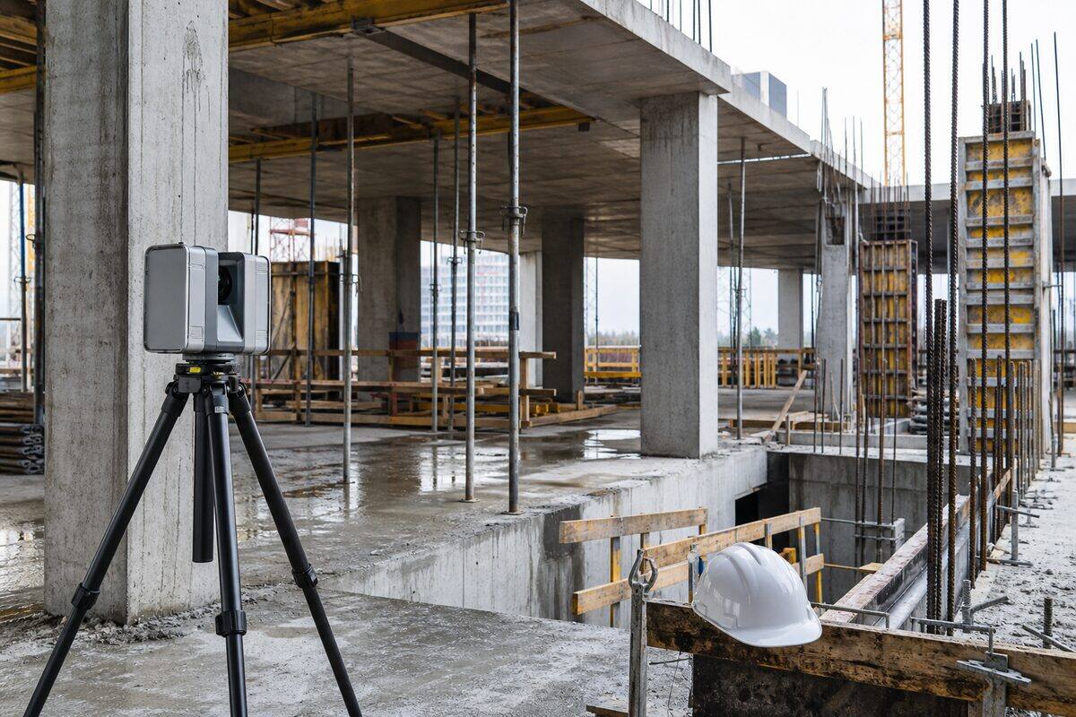
Construction verification scanning compares as-built site conditions against design intent using 3D laser measurement. Brisbane Point Cloud delivers progress documentation, deviation analysis, and defect detection for construction projects across Australia.
Overview
Construction Verification Scanning explained
Construction verification scanning compares what was actually built against the design model, catching deviations before they compound into expensive rework. We scan at each critical stage with the Trimble X7 and Trimble X9 for precise structural and facade capture and the NavVis MLX for rapid floor-plate coverage, then align the as-built point cloud to the design model and report every element that falls outside tolerance. The output is colour-coded deviation maps, pass or fail reports, and a permanent dimensional record at every epoch.
The value comes from timing the scans to the construction programme. Common stages are after excavation and piling to verify founding levels, after formwork placement to check position before the pour, after the pour to confirm slab levels and wall plumb, after steel erection to verify member positions and connections, during facade installation to track panel positions and gap tolerances, and at practical completion for a full as-built record. Scanning at each stage creates evidence that protects progress claims and catches grid and level errors while they are still cheap to fix.
Tolerances are set against real standards. AS 3600 permits +/-10mm positional tolerance for formed concrete and tighter limits for surface regularity; AS 4100 specifies +/-3 to +/-5mm for steel member positions depending on element type; floor flatness is measured to ASTM E1155 and reported as FF and FL numbers. Our scanning detects deviations of 2 to 3mm, which is always finer than the construction tolerance being verified, so the measurement itself is never the limiting factor.
Reporting is built around construction deadlines. Standard deviation analysis is delivered within two to three business days, and for time-critical situations such as a pour scheduled against the next slab, we provide same-day preliminary results: a visual deviation map and a summary of out-of-tolerance elements within hours of scanning. We accept design models in Revit, IFC, AutoCAD, Navisworks, Tekla, 12d, and Civil 3D, and where only 2D drawings exist we build a simple reference model to enable automated comparison.
Survey control & accuracy
AHD levels and MGA2020 coordinates
As-built scans are aligned to the project coordinate system so deviation analysis is meaningful. We register each scan to the building grid or MGA2020 coordinates using common reference points such as survey marks and grid lines, with levels reduced to the Australian Height Datum (AHD). A registered surveyor on staff oversees control where setout verification or dispute-grade evidence is required. Alignment accuracy is verified before analysis, and every report documents the control and residuals behind the result.
Capabilities
What we deliver
- As-built vs design comparison with colour-coded deviation maps
- Construction progress documentation at each build stage
- Concrete pour verification (formwork position, slab levels, wall plumb)
- Steel erection verification (member positions, bolt holes, connections)
- Facade installation tracking (panel positions, gap tolerances)
- Floor flatness and levelness measurement (FF/FL to ASTM E1155)
- Defect documentation with precise spatial location data
Equipment Used
Deliverables
- Colour-coded deviation maps (point cloud vs design model)
- Pass/fail reports against specified tolerances
- Progress comparison imagery (date-stamped overlays)
- Floor flatness/levelness reports (FF/FL numbers)
- Defect register with 3D coordinates and photographs
- As-built point cloud at each scan epoch
Technical specifications
The numbers behind the data
- Deviation detection
- 2 to 3mm
- Concrete tolerance ref
- AS 3600 (+/-10mm typical formed)
- Steel tolerance ref
- AS 4100 (+/-3 to +/-5mm)
- Floor flatness
- FF/FL to ASTM E1155
- Model formats accepted
- Revit, IFC, DWG, Navisworks, Tekla, 12d
- Standard reporting
- 2 to 3 business days
- Urgent option
- Same-day preliminary deviation map
- Datum
- Project grid or MGA2020, AHD levels
Standards & compliance
Standards we work to
Positional and surface tolerances for formed concrete verification.
Member position and connection tolerances for steel erection checks.
Methodology for FF/FL measurement and reporting.
Governs alignment of as-built data to the design model.
Datum for aligning scans to project grid and coordinates.
Our Process
How we work
Tolerance Definition
We review the design model and specification to establish pass/fail tolerances for the elements being verified. Industry standards (AS 3600, AS 4100) and project-specific tolerances guide the acceptance criteria.
Site Scan
We scan the construction at the agreed stage. Timing is coordinated with the construction programme so scans capture the relevant elements before they are covered or inaccessible.
Model Alignment
The as-built point cloud is aligned to the design model coordinate system using common reference points (survey marks, grid lines, or building geometry). Alignment accuracy is verified before analysis.
Analysis & Reporting
Each element is compared against the design model. Deviations outside tolerance are flagged, located, and quantified. Reports include visual deviation maps and a summary table of pass/fail results per element or zone.
FAQs
Common questions
What construction tolerances can scanning verify?
Our scanning equipment detects deviations as small as 2-3mm, which is well within the tolerances specified by Australian construction standards. AS 3600 (Concrete Structures) permits +/-10mm positional tolerance for formed concrete elements and +/-5mm for surface regularity. AS 4100 (Steel Structures) specifies +/-3mm to +/-5mm for member positions depending on element type. We report all deviations and flag those exceeding the applicable tolerance. For floor flatness, we measure to ASTM E1155 methodology and report FF/FL numbers. The scanning accuracy is always finer than the construction tolerance being verified.
At what construction stages should scanning be done?
The optimal scan schedule depends on what you need to verify. Common scan stages include: after excavation and piling (verify founding levels), after formwork placement (verify position before pour), after concrete pour (verify slab levels and wall positions), after steel erection (verify member positions and connections), during facade installation (verify panel positions and gap sizes), and at practical completion (full as-built record). Scanning at each stage creates a permanent record and catches deviations before they compound. For high-value projects, monthly progress scans provide continuous documentation and early warning of tolerance drift.
How quickly can you deliver deviation reports?
Standard turnaround for a deviation analysis report is 2-3 business days from scan date. For time-critical situations (e.g., concrete pour verification where the next pour is scheduled), we offer same-day preliminary results: a visual deviation map and summary of any out-of-tolerance elements, delivered within hours of scanning. The full detailed report follows within 2 days. We understand construction programmes and schedule our resources to meet your programme deadlines.
What design model formats do you work with?
We accept design models in Revit (.rvt), IFC, AutoCAD (.dwg), Navisworks (.nwd/.nwc), Tekla (.ifc export), 12d, Civil 3D, and Bentley formats. The model is imported into our analysis software and aligned to the scan data. If your model is not in a compatible format, we can usually convert it. For concrete works where only 2D drawings exist, we create a simple 3D reference model from the drawings to enable automated comparison. The key requirement is that the design intent is defined geometrically at the level of detail being verified.
Can scanning replace traditional survey for construction setout verification?
Scanning complements rather than replaces setout survey. Setout is done point-by-point using total station (marking positions on site for the builder to build to). Verification scanning checks what was actually built after construction. The two work together: the surveyor sets out, the builder constructs, and the scanner verifies. Scanning adds value by checking every surface rather than just discrete points, revealing issues like bowing, rotation, or surface irregularity that point checks would miss. For quality assurance programmes, periodic scanning between traditional survey checks provides continuous spatial verification.
Industries
Industries we serve with construction verification scanning
Construction & Developers
Construction teams need reliable as-built geometry before concrete is poured, before services are closed in, and before handover. Legacy drawings are often wrong. Site changes happen daily. A registered point cloud gives the superintendent, engineer, and BIM coordinator one shared reference that matches what is on site today.
IndustryCivil & Infrastructure
Infrastructure assets need geometry that matches field conditions: bridge soffits, culvert invert levels, road corridors, retaining walls, and drainage networks. Traditional pick-up is slow on complex structures. Laser scanning captures millions of points in hours, giving engineers a complete record for assessment, design, and asset management.
IndustryInsurance & Legal
Insurance claims, contract disputes, and defect litigation need an independent, measurable record of building condition. Photographs alone lack scale and completeness. A registered point cloud captures the full scene with date-stamped metadata, giving adjusters, lawyers, and expert witnesses a dataset they can measure repeatedly.
Related Pages
Build the right scanning package
Civil & Infrastructure
LiDAR surveys for roads, bridges, rail corridors, and civil earthworks. From design verification to as-built documentation, we capture infrastructure at any scale.
ServiceIndustrial & As-Built
Comprehensive as-built documentation for factories, processing plants, warehouses, and mechanical installations. Capture every pipe, duct, and structural member in 3D.
Service3D Laser Scanning & Point Cloud Survey
Need a building, structure, or site captured in 3D? Our laser scanning service turns physical spaces into precise digital models. We handle everything from quote through to delivery: you get clean, usable point cloud data ready for your software.
ServiceTopographic Survey Brisbane
Terrain models, contour plans, and earthworks volumes delivered from airborne LiDAR. We survey land at 50x the detail of traditional total station methods, penetrate vegetation canopy to map ground level, and produce contours at intervals as fine as 0.25m.
Locations
Coverage by city
Brisbane is our main base, with scheduled project trips to major Australian cities for larger scanning scopes.
Project Proof
Related scanning case studies
Get a quote for construction verification scanning
Tell us about your project and we will provide a fixed-price proposal within one business day.